
I've been accused of never giving a short answer, this one will be no exception. Why use ten words when a hundred will do 
The sensors I use are DS18B20, enclosed in a stainless steel sleeve, with about 3 feet of wire. They are rugged, reliable and very inexpensive. I purchased all of mine and about 100 for other friends and family on eBay. They arrive from China within two weeks and are about $17 for 10 delivered. This is the merchant I have been using.
I use the EDS OWServer for my temperature monitoring. While Greig's Arduino plug-in does a great job with OneWire temperature sensors, there are some compelling reasons to use the OWServer.
One of the problems with OneWire devices is that they consume more current during the calculation phase of their operation. With a single device and a short run of cable a 2.2k-4.7k resistor works fine for the data pull-up. When you are connecting two dozen devices on 100 feet or more of cable, the pull up gets a lot more complicated. The OWServer uses a dynamic circuit to maintain current and voltage on the pull-up especially during the critical calculation phase of operation. It has a nice web interface that can tell you at a glance the status of your OneWire network(s).
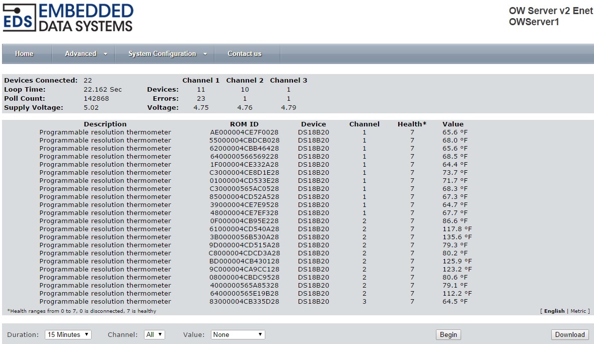
Here is a screenshot from one of mine showing 22 devices. It shows you the health of each device, loop times (update frequency) and other data. If you look at the temperatures it is easy to see that a DHW event was just completed as the tank (3B0000056B530A28) is 135.6, the boiler supply (9C000004CA9CC128) is 123.2 and the boiler return (6400000565E19B28) is 112.2. That screenshot was taken about 15 minutes after the cycle was completed.
Click on any device and you get more detail on the device.
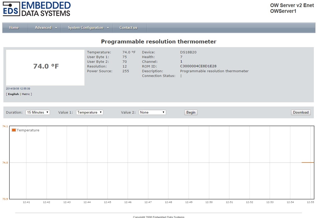
There are also decent graphing capabilities on the web interface. The graphing is real time, not archival. Since it is queried with simple HTTP Get actions, you can access the web interface while it still actively updates HomeSeer.
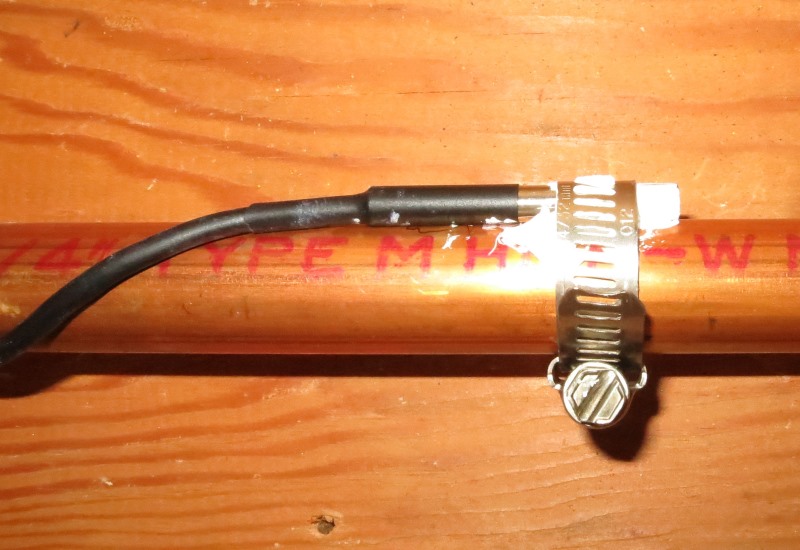
The temperature sensors are attached to the copper piping with hose clamps and a dollup of heat sink compound. The heat sink compound is probably overkill, but as long as I was at it - what the heck.
I had a friend use the same method on his PEX system and says he gets very good accuracy even with plastic pipe. Since relative temperatures are often as valuable as absolute readings, the outside temperature of the pipes (whether copper or plastic) is adequate for monitoring. For my protection from the pipes freezing, I am only generally concerned with the pipe temperature and just keep it above 40 on cold days and 50 on really cold days. During December-February it can get below 0 in Denver, so I bump up the threshold at an outside temperature of 20 degrees or less.
Since I initially wrote the posts starting this thread I have made some discoveries and changes. One thing I discovered was lost energy in the heating of our domestic hot water (DHW) in the summertime. We have a single 160,000 BTU boiler that takes care of our baseboard heat and DHW. In the wintertime the boiler is in fairly constant use, but in the spring and summer it is used very intermittently and sometimes only for DHW. The normal way for these systems to function is to call for heat to the indirect water heater. That heat call opens a zone valve and the limit switch on the zone valve starts the circulator. The burner is controlled thermostatically so that it runs until its high limit (200-degrees) is hit as long as there is zone demand. When I automated the system, I look at every zone valve status, zone valve actuator, temperatures at the supply and return of the boiler and all 9 zones. I also control the circulator and burner independently. Initially I was concerned about short burner cycles in the winter and that worked very well by delaying burner action based upon boiler supply temperature and zone demand. I also created sleep and work times for DHW, where it would not respond to demand, until it was near the times we use hot water.
One thing I discovered when I was looking at temperature trends was the fact that in the summer, the boiler would get almost to its high limit every time there was demand for DHW heat. If I triggered the DHW to come on at 110 degrees, with a goal of 130+ degree water (we like ours hot), I needed to shut the DHW zone valve at 126-degrees. The energy from the 180+ degree boiler water in the indirect coil would continue heating the DHW another 4 or 5 degrees. The problem is that there is a cast iron boiler with quite a few gallons of water sitting at 180+ degrees doing absolutely nothing other than slowly radiating that heat into the boiler closet and basement. The change in function is that we now trigger demand at 115-degrees when there is or has been no heat demand - I know this because of the supply and return temperatures of the boiler as well zone demand for all of the heat zones. I still trigger at 110 when the boiler is already hot. This opens the zone valve for DHW, starts the circulator and fires the burner. In the summer or when there is no heat demand the DHW program shuts off the burner at 122-degrees, but leaves the zone valve open and the circulator running. This continues for 9 minutes. At the end of the process we have boiler supply, return and DHW temperatures all at 135-degrees. We have recovered a significant portion of the energy that would otherwise have been radiated into the room by the boiler. Looking at the raw data we have reduced the boiler burn times for DHW by 40%, effectively reducing our summer hot water costs by that same percentage. Granted, it is not a lot, but still amounts to about $10 per month in summer savings. In the winter when there is other heat demand, the program shuts the DHW zone valve at 128 degrees. The heat automation takes care of the circulator and burner.
I have expanded the use of OneWire devices. I have not figured out what to do with the data yet, but I monitor my Air Conditioning system as well. We have 2 LG Mini-split ductless systems. A single system for the family room/dining room/kitchen and a multi-split for the bedrooms. I have sensors on the supply (liquid) and return (gas) lines to the outdoor units, the ambient and exhaust air for both outside units and the return and outlet air for the four indoor air handlers. The data did show me I was low on Freon on the multi unit because of lower temperature drop on the air handlers. It could also be seen in the line temperatures. Hopefully I can hook into HomeSeer's new graphing capabilities down the road.
As you can tell I love granular data, sometimes it is useful, sometimes just interesting - but more data is more gooder
The sensors I use are DS18B20, enclosed in a stainless steel sleeve, with about 3 feet of wire. They are rugged, reliable and very inexpensive. I purchased all of mine and about 100 for other friends and family on eBay. They arrive from China within two weeks and are about $17 for 10 delivered. This is the merchant I have been using.
I use the EDS OWServer for my temperature monitoring. While Greig's Arduino plug-in does a great job with OneWire temperature sensors, there are some compelling reasons to use the OWServer.
- has a direct Ethernet connection
- supports up to 23 devices per server with up to 3 separate inputs
- supports very long sensor runs using CAT5 cable. They claim up to 1000'
One of the problems with OneWire devices is that they consume more current during the calculation phase of their operation. With a single device and a short run of cable a 2.2k-4.7k resistor works fine for the data pull-up. When you are connecting two dozen devices on 100 feet or more of cable, the pull up gets a lot more complicated. The OWServer uses a dynamic circuit to maintain current and voltage on the pull-up especially during the critical calculation phase of operation. It has a nice web interface that can tell you at a glance the status of your OneWire network(s).
Here is a screenshot from one of mine showing 22 devices. It shows you the health of each device, loop times (update frequency) and other data. If you look at the temperatures it is easy to see that a DHW event was just completed as the tank (3B0000056B530A28) is 135.6, the boiler supply (9C000004CA9CC128) is 123.2 and the boiler return (6400000565E19B28) is 112.2. That screenshot was taken about 15 minutes after the cycle was completed.
Click on any device and you get more detail on the device.
There are also decent graphing capabilities on the web interface. The graphing is real time, not archival. Since it is queried with simple HTTP Get actions, you can access the web interface while it still actively updates HomeSeer.
The temperature sensors are attached to the copper piping with hose clamps and a dollup of heat sink compound. The heat sink compound is probably overkill, but as long as I was at it - what the heck.
I had a friend use the same method on his PEX system and says he gets very good accuracy even with plastic pipe. Since relative temperatures are often as valuable as absolute readings, the outside temperature of the pipes (whether copper or plastic) is adequate for monitoring. For my protection from the pipes freezing, I am only generally concerned with the pipe temperature and just keep it above 40 on cold days and 50 on really cold days. During December-February it can get below 0 in Denver, so I bump up the threshold at an outside temperature of 20 degrees or less.
Since I initially wrote the posts starting this thread I have made some discoveries and changes. One thing I discovered was lost energy in the heating of our domestic hot water (DHW) in the summertime. We have a single 160,000 BTU boiler that takes care of our baseboard heat and DHW. In the wintertime the boiler is in fairly constant use, but in the spring and summer it is used very intermittently and sometimes only for DHW. The normal way for these systems to function is to call for heat to the indirect water heater. That heat call opens a zone valve and the limit switch on the zone valve starts the circulator. The burner is controlled thermostatically so that it runs until its high limit (200-degrees) is hit as long as there is zone demand. When I automated the system, I look at every zone valve status, zone valve actuator, temperatures at the supply and return of the boiler and all 9 zones. I also control the circulator and burner independently. Initially I was concerned about short burner cycles in the winter and that worked very well by delaying burner action based upon boiler supply temperature and zone demand. I also created sleep and work times for DHW, where it would not respond to demand, until it was near the times we use hot water.
One thing I discovered when I was looking at temperature trends was the fact that in the summer, the boiler would get almost to its high limit every time there was demand for DHW heat. If I triggered the DHW to come on at 110 degrees, with a goal of 130+ degree water (we like ours hot), I needed to shut the DHW zone valve at 126-degrees. The energy from the 180+ degree boiler water in the indirect coil would continue heating the DHW another 4 or 5 degrees. The problem is that there is a cast iron boiler with quite a few gallons of water sitting at 180+ degrees doing absolutely nothing other than slowly radiating that heat into the boiler closet and basement. The change in function is that we now trigger demand at 115-degrees when there is or has been no heat demand - I know this because of the supply and return temperatures of the boiler as well zone demand for all of the heat zones. I still trigger at 110 when the boiler is already hot. This opens the zone valve for DHW, starts the circulator and fires the burner. In the summer or when there is no heat demand the DHW program shuts off the burner at 122-degrees, but leaves the zone valve open and the circulator running. This continues for 9 minutes. At the end of the process we have boiler supply, return and DHW temperatures all at 135-degrees. We have recovered a significant portion of the energy that would otherwise have been radiated into the room by the boiler. Looking at the raw data we have reduced the boiler burn times for DHW by 40%, effectively reducing our summer hot water costs by that same percentage. Granted, it is not a lot, but still amounts to about $10 per month in summer savings. In the winter when there is other heat demand, the program shuts the DHW zone valve at 128 degrees. The heat automation takes care of the circulator and burner.
I have expanded the use of OneWire devices. I have not figured out what to do with the data yet, but I monitor my Air Conditioning system as well. We have 2 LG Mini-split ductless systems. A single system for the family room/dining room/kitchen and a multi-split for the bedrooms. I have sensors on the supply (liquid) and return (gas) lines to the outdoor units, the ambient and exhaust air for both outside units and the return and outlet air for the four indoor air handlers. The data did show me I was low on Freon on the multi unit because of lower temperature drop on the air handlers. It could also be seen in the line temperatures. Hopefully I can hook into HomeSeer's new graphing capabilities down the road.
As you can tell I love granular data, sometimes it is useful, sometimes just interesting - but more data is more gooder


Comment