Announcement

Collapse
No announcement yet.

Home Automation fits and starts - mostly success...

Collapse
X
 
  • Filter
  • Time
  • Show
Clear All
new posts

  • Mwillis
    replied
    Originally posted by rprade View Post
    Ben and Paul are both very helpful and responsive to emails, if you have any questions. I will also be happy to discuss it here. At two years in, it remains the best single purchase I made in this whole process. I hope to get around to updating this thread, the project has matured nicely.
    I plan on doing a post similar to this. I'm still in the testing phase. Figuring out what works. I am actually doing a ton of advanced things. Its quite the challenge cause not only am I doing all this but I'm attempting to reduce the energy foot print as much as possible. This is very challenging as I am also wanting this to be fully Voice controlled, with independently audio output and input. I am planning on using a XAP800 for audio routing. and kinects for mic input, VERY hard to do with a Virtual Machine.

    Who is Ben and Paul?

    Leave a comment:


  • randy
    replied
    Ben and Paul are both very helpful and responsive to emails, if you have any questions. I will also be happy to discuss it here. At two years in, it remains the best single purchase I made in this whole process. I hope to get around to updating this thread, the project has matured nicely.

    Leave a comment:


  • Mwillis
    replied
    Originally posted by rprade View Post
    Brultech's manual is very comprehensive, perhaps you don't have it. I tried to attach it but it is too big. I don't know where it is on their server but have uploaded a copy to mine. www.prades.net/misc/GEM-Man_ver_4.0_.pdf

    You have to identify your CT as to which type they are. CT installation and identification begins on page 18 of the manual. I used mostly CT40s which are "type B" CTs. A Type B outputs a current signal. On 240 volt circuits like our dryer, air conditioners and stove, where there was no current flow through neutral, I used a single CT and configured it accordingly. For two sub-panels where there was dissimilar loading on the two phases, I did cut and solder the leads of the two CTs together so that it was easier to connect. If I remember correctly the "type B" CTs wire in phase and in parallel, so I soldered them together to a single pair of leads. I used heat shrink tubing on the joints. That was only to make the connection to the GEM board a little cleaner and easier to connect.

    For a single temperature probe inside the GEM cabinet I used a DS18B20 on a lead. They are about $18 for 10 shipped from China on eBay. The GEM will reliably support 4-6 probes, depending on the lead length and topology. I chose to go with EDS OneWire servers for my temperature monitoring. They are more forgiving of longer leads and unusual topology. I have three servers with a total of about 50 probes.

    I didn't use water flow measurement, but you can use any flow meter that generates pulses relative to flow. They are described on page 5 and 6 of the attached manual. I cannot think immediately of a way to do it wireless, but a 2-conductor wire can go a long way for slow pulses. I would probably terminate it in an opto-isolator to protect the GEM - a long wire is a very good antenna for ESD in a lightning storm.
    Thank you. No I did not have the manual. I only had a sheet of paper that came with the product that briefly describes things but not in the detail as what I just Downloaded from you. Mine is a newer model but the info I need is the same.

    Leave a comment:


  • randy
    replied
    Originally posted by Mwillis View Post
    Hello, Thank you so much for posting your info. I am actually following your lead. I was needing to know. Did you solder the dual CT together? also looks like you cut the leads. also I flipped the polarity on the duals. If you could explain the wiring in more detail their instructions are a bit blah to me.

    I would also like to know your thoughts on the temp sensor. Seems they are out of them. Is there other options?

    I also would like to meter my water. I am on a my own well. However, it would be nice to meter the amount of water for the filters. But I would need a way to wirelessly connect such devices to this as the well is in another building. any thoughts on this would be great.
    Brultech's manual is very comprehensive, perhaps you don't have it. I tried to attach it but it is too big. I don't know where it is on their server but have uploaded a copy to mine. www.prades.net/misc/GEM-Man_ver_4.0_.pdf

    You have to identify your CT as to which type they are. CT installation and identification begins on page 18 of the manual. I used mostly CT40s which are "type B" CTs. A Type B outputs a current signal. On 240 volt circuits like our dryer, air conditioners and stove, where there was no current flow through neutral, I used a single CT and configured it accordingly. For two sub-panels where there was dissimilar loading on the two phases, I did cut and solder the leads of the two CTs together so that it was easier to connect. If I remember correctly the "type B" CTs wire in phase and in parallel, so I soldered them together to a single pair of leads. I used heat shrink tubing on the joints. That was only to make the connection to the GEM board a little cleaner and easier to connect.

    For a single temperature probe inside the GEM cabinet I used a DS18B20 on a lead. They are about $18 for 10 shipped from China on eBay. The GEM will reliably support 4-6 probes, depending on the lead length and topology. I chose to go with EDS OneWire servers for my temperature monitoring. They are more forgiving of longer leads and unusual topology. I have three servers with a total of about 50 probes.

    I didn't use water flow measurement, but you can use any flow meter that generates pulses relative to flow. They are described on page 5 and 6 of the attached manual. I cannot think immediately of a way to do it wireless, but a 2-conductor wire can go a long way for slow pulses. I would probably terminate it in an opto-isolator to protect the GEM - a long wire is a very good antenna for ESD in a lightning storm.

    Leave a comment:


  • Mwillis
    replied
    Hello, Thank you so much for posting your info. I am actually following your lead. I was needing to know. Did you solder the dual CT together? also looks like you cut the leads. also I flipped the polarity on the duals. If you could explain the wiring in more detail their instructions are a bit blah to me.

    I would also like to know your thoughts on the temp sensor. Seems they are out of them. Is there other options?

    I also would like to meter my water. I am on a my own well. However, it would be nice to meter the amount of water for the filters. But I would need a way to wirelessly connect such devices to this as the well is in another building. any thoughts on this would be great.
    Attached Files
    Last edited by Mwillis; April 14, 2016, 05:22 PM.

    Leave a comment:


  • TeleFragger
    replied
    WOW Great read!
    so stoked and motivated to get my hs stuff going once my kitchen / house remodel is done.

    Leave a comment:


  • randy
    replied
    Originally posted by KandB View Post
    Thanks for this series of posts, Randy. We're about where you were when you first posted - about 60 days in Homeseer, getting comfortable with it, working through the nuances, figuring out what we want it to be someday. You've provided a couple of terrific takeaways for us: the practical use of the GEM and the EDS/one-wire setup are of particular interest.

    Great stuff, Randy!

    -Bill
    I'm glad it gave you ideas. It has since evolved a lot. I will try to post an update soon.

    Leave a comment:


  • randy
    replied
    Originally posted by ServiceXp View Post
    I know those pictures are old, but I thought I might bring it to your attention.

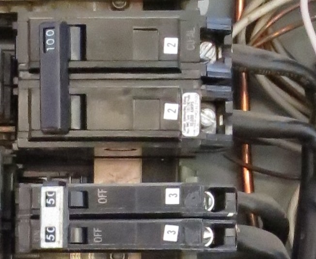
    It looks like there are 1 or 2 aluminum strands that are above the lug on the 100 amp breaker?
    I missed this post when you made it back in September. Thanks for pointing that out, but I think it is a trick of the light in that photo. Here is a crop from the one at the top of the post


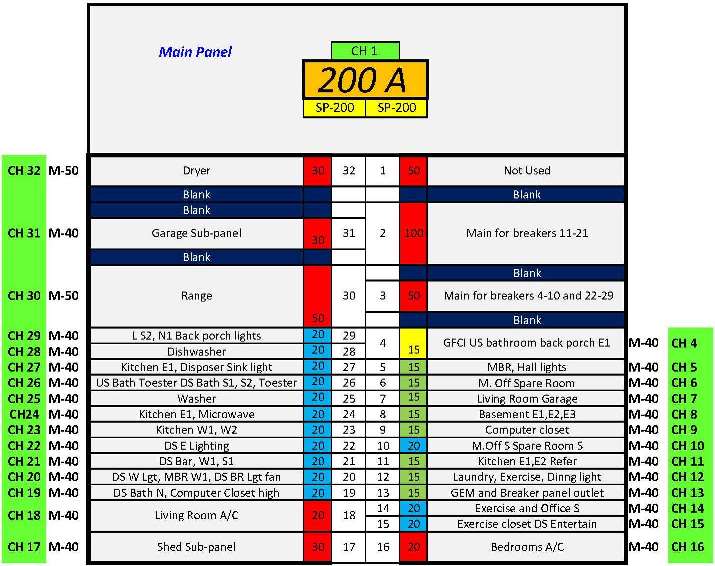
    As you can see, it is clean. If I remember correctly those are not stranded, they are bus bars. They were provided with the panel from GE. It was originally designed as a split 200A panel and the lower half was for electric baseboard heating. The upper 100A breaker is for the bus supplying breakers 11-21 and the 50A breaker below supplies the bus for 4-10 and 22-29. The 100A was for heat and the 50A was for the rest of the house. The house was built in the early 70's. I have since had natural gas run to the house and converted the home to hot water baseboard heating. The lower half of the panel is now providing circuits for the basement, air conditioners and other additions.

    Leave a comment:


  • KandB
    replied
    Thanks for this series of posts, Randy. We're about where you were when you first posted - about 60 days in Homeseer, getting comfortable with it, working through the nuances, figuring out what we want it to be someday. You've provided a couple of terrific takeaways for us: the practical use of the GEM and the EDS/one-wire setup are of particular interest.

    Great stuff, Randy!

    -Bill

    Leave a comment:


  • ServiceXp
    replied
    I know those pictures are old, but I thought I might bring it to your attention.

    It looks like there are 1 or 2 aluminum strands that are above the lug on the 100 amp breaker?
    Attached Files

    Leave a comment:


  • randy
    replied
    Originally posted by ecuboss View Post
    Ok and one more related question;
    For inputs via the arduino into HS, does HS have to keep polling the arduino for input values or does a change of input immediately trigger a device change in HS?

    I'm thinking a low voltage light switch that triggers an input which then triggers an output to turn a light on. If its polling, it can take a while to "see" that the input has changed which will impact WAF.
    It is almost instant. To test I built an event loop. The first event triggered by a closed input activating an output turning on a relay causing the NC contacts to open the Arduino input. That open input triggered a second event turning off the relay. Then the loop starts over. The full loop represented four round trips and the time for two events to trigger. It ran at about 4 cycles per second.

    Leave a comment:


  • ecuboss
    replied
    Ok and one more related question;
    For inputs via the arduino into HS, does HS have to keep polling the arduino for input values or does a change of input immediately trigger a device change in HS?

    I'm thinking a low voltage light switch that triggers an input which then triggers an output to turn a light on. If its polling, it can take a while to "see" that the input has changed which will impact WAF.

    Leave a comment:


  • randy
    replied
    Originally posted by ecuboss View Post
    Nice write up.
    Regarding the arduino boards and relays. Does it remember state? By this I mean, if you set a relay to be on and there is a power failure on the arduino or it disconnects from the network or you reboot it, does it remember what state all its outputs were and put them back to that state when it recovers?

    I ask, as I currently use the homeseer ADIO100 I/O board - which does remember state if its unplugged or cycled - and this is quite important if its running your heating or opening a door!
    Yes. If it is disconnected from the network, power cycled or reset, it will restore the state of its outputs as soon as it communicates with HomeSeer. If it loses communication with HomeSeer, all of the outputs will remain in the last state until communication is restored.

    Leave a comment:


  • ecuboss
    replied
    Nice write up.
    Regarding the arduino boards and relays. Does it remember state? By this I mean, if you set a relay to be on and there is a power failure on the arduino or it disconnects from the network or you reboot it, does it remember what state all its outputs were and put them back to that state when it recovers?

    I ask, as I currently use the homeseer ADIO100 I/O board - which does remember state if its unplugged or cycled - and this is quite important if its running your heating or opening a door!

    Leave a comment:


  • randy
    replied
    Originally posted by Vincenttor View Post
    Snip...

    But if i do it like this i would hear 2 clicks in a room, not that bad of course but i would have to add more wires to supply the power for the big/end relay.
    Most of them rated 30Amps or more are using 12 or 24 Volt.
    What is the problem if i take 2 lines that switch the end relay, so that it is like drawing 1 the cable is longer from the relay board to the end relay.
    I wouldn't think you would need the relay board in addition to the relay at the socket. Just drive a relay like below (30A rated) directly from the Arduino. The control pins from the Arduino would not contain data, so they could travel a great distance. With a couple of capacitors, I really don't think interference would be a problem. I ran about 150 feet of CAT cable from an Arduino to a relay for a temporary control over the summer and it worked flawlessly. The relay below cost me US$4.48 shipped from China. It can be configured to trigger with high or low and is powered by 5-volts.
    Attached Files

    Leave a comment:

Working...
X